Static Timing Analysis Interview Exercises: Setup, Hold, and Constraint Debugging
Quick Overview
Prepare for static timing analysis interview questions with worked setup and hold slack calculations, clock skew examples, constraint debugging, and practical verification steps.
Static timing analysis interview questions test whether you can connect clock edges, data-path delay, and design intent. The important skill is not memorizing one slack formula; it is stating which launch and capture edges you are comparing and what the constraints say the circuit must do.
This exercise covers setup and hold checks, clock skew, and the difference between a false path and a multicycle path. The examples are teaching scenarios, not claims about a particular employer’s interview bank.
For adjacent practice, browse the PracHub technical question bank.
Key takeaways
- Draw the launch and capture clock edges before calculating slack.
- Setup checks the latest data arrival against a capture requirement; hold checks the earliest data arrival against a same-cycle requirement.
- Positive capture-minus-launch skew generally helps setup and can make hold harder, assuming the usual edge relationship.
- A false-path exception removes a timing requirement only when the path is functionally not required; a multicycle exception changes the intended capture edge.
- Always inspect the tool’s path report and the paired hold check after changing constraints.
How do you calculate setup slack?
For a simple register-to-register path, the data arrival includes launch-clock arrival, clock-to-Q delay, combinational cell delay, and interconnect delay. The required arrival is based on the selected capture edge, capture-clock arrival, setup time, and uncertainty. Exact report conventions differ, so show your clock-edge assumptions and reconcile them with the static-timing tool.
Assume a 1.00 ns clock period, 0.10 ns launch-clock arrival, 0.18 ns capture-clock arrival, 0.06 ns setup time, 0.12 ns uncertainty, and 0.80 ns total clock-to-Q plus data-path delay. Data arrives at 0.90 ns. The next capture requirement is 1.00 + 0.18 − 0.06 − 0.12 = 1.00 ns, giving 0.10 ns setup slack under this convention. If capture skew were zero, the same arithmetic would leave 0.02 ns; the clock relationship matters.
What changes for a hold check?
Hold is a minimum-delay check. The newly launched data must not reach the capture register too early relative to the relevant capture edge and hold requirement. A design can pass setup and fail hold: adding pipeline depth or slowing a maximum path does not automatically fix a minimum path.
Use the report’s minimum data path, launch and capture clock arrivals, hold time, and uncertainty. Then identify whether the failure is local to one path or repeated across a clock domain. A common physical remedy is to add delay to a short data path, but the fix must be checked against setup timing and the implementation flow.
Is the path false, or does it need multiple cycles?
A false path is a statement about functional timing intent: the ordinary synchronous relationship does not apply to that path. Examples can include a properly constrained asynchronous crossing, but only when the design’s synchronization structure supports that interpretation. A multicycle path says the receiving logic intentionally captures the value on a later edge. It is not a generic way to suppress a failing report.
Suppose a control signal is sampled only on every second destination cycle. Before declaring a two-cycle setup path, explain how the receiving enable guarantees that behavior, identify the launch and capture edges, and inspect the corresponding hold relationship. A constraint that fixes setup while making hold invalid is not a correct constraint set.
| Symptom | Question to ask | Evidence |
|---|---|---|
| Setup violation | Which edge is the intended capture? | Arrival/required times, skew, uncertainty |
| Hold violation | Is the minimum path too short or the clock relation unexpected? | Minimum-delay path and clock-tree report |
| Many unconstrained paths | Are clocks and I/O delays defined? | Constraint coverage and clock report |
| Exception removes many paths | Does the exception match functional intent? | Expanded exception targets and design protocol |
How should you debug a suspicious exception?
Start with the exact startpoint and endpoint. Expand the constraint to see what objects it matches, then compare that set with the intended logic. A broad wildcard can unintentionally exempt neighboring paths. Check generated clocks, clock groups, input/output delays, and whether the report labels the path as constrained or unconstrained.
Ask what test or protocol would fail if the path were actually required to meet timing. For asynchronous crossings, inspect synchronizer structure and clock-domain methodology instead of treating every crossing as automatically false. For multicycle paths, verify both setup and hold semantics against the receiving enable or handshake.
What is a strong interview workflow?
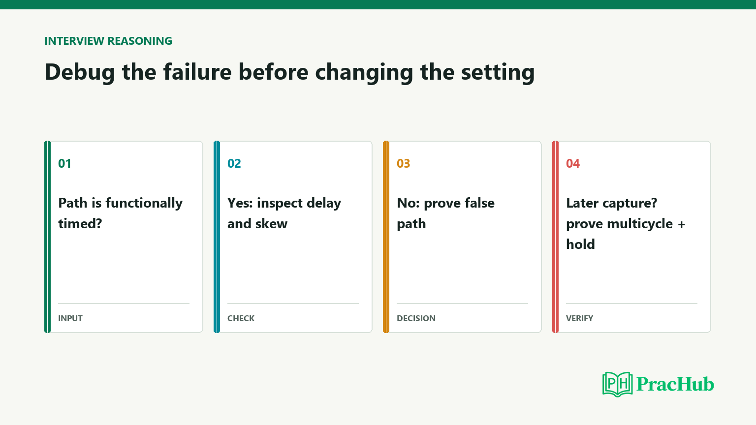
- State the clock period, active edges, launch/capture relationship, and uncertainty.
- Separate maximum-delay setup analysis from minimum-delay hold analysis.
- Calculate one worked path with units and show where skew enters.
- Inspect the actual path report before changing an exception or delay.
- Re-run setup and hold checks after the change, and verify the exception matches the functional design.
Intel’s timing-constraint documentation is a useful reference for how clock relationships and constraints are represented in a real implementation flow: Intel timing constraints reference. The current Quartus Timing Analyzer guide explains path relationships, setup and hold checks, and constraint analysis for its supported version.
The concise answer to “How do you debug a setup or hold violation?” is: identify the path and clock edges, validate the constraint model, calculate the relevant max or min check, change the smallest justified design or constraint element, and confirm both checks afterward.
How do you move from a failing path to a defensible timing fix?
In a timing-analysis interview, do not jump from negative slack to “reduce logic depth.” First classify the path: register-to-register, input-to-register, register-to-output, or a clock path. Then check that both clocks and the relevant I/O delays are defined. A missing or incorrectly generated clock can make a report look clean while leaving real paths unconstrained.
For a setup failure, compare the worst path’s cell and net delay, fanout, transition, and clock arrival. If cell delay dominates, logic restructuring or a different cell may help; if net delay dominates, placement, fanout, or congestion may be the limiting factor. A useful answer names the evidence that distinguishes these cases instead of prescribing a fix from slack alone.
For a hold failure, inspect minimum delay and clock skew, then consider whether the physical-design flow can insert delay cells. Do not “fix” hold by changing a functional exception. After every proposed change, rerun both setup and hold across relevant corners, because a change that improves one check can worsen another.
A concise report-back is: “The path is constrained, the failing check is setup, net delay dominates, and the endpoint captures on the next active edge. I would test a localized placement or fanout remedy, then compare setup and hold across corners.” That answer is specific, falsifiable, and safer than a tool-command recital.
Comments (0)