NVIDIA ASIC Verification New Grad Interview: RTL Reasoning, Testbenches, and Debugging
Quick Overview
Use official NVIDIA Emulation-team role evidence and an original counter exercise to practice RTL contracts, testbench observation, coverage, and debugging.
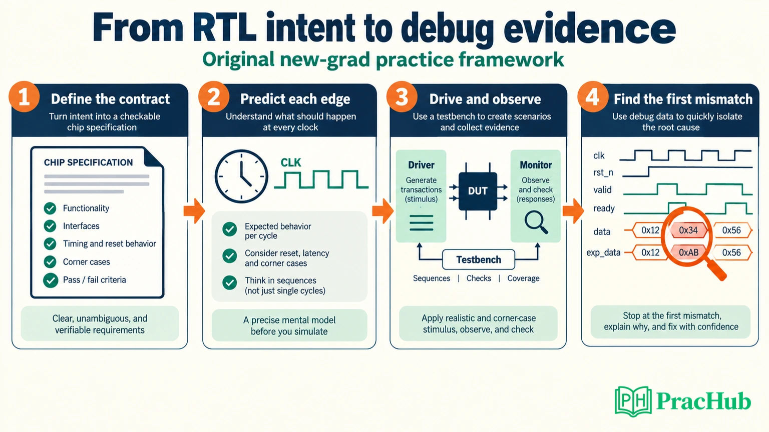
For an NVIDIA ASIC Verification new grad interview, prepare to explain how you know an RTL design is correct. That means translating a specification into observable behavior, constructing a testbench that can detect mistakes, and following a failure back to its first incorrect state transition.
This guide develops those skills through an original two-bit counter exercise. The block is deliberately small: its reset, clear, enable, and wraparound behavior provide enough material to expose weak reasoning without requiring a large protocol specification. For broader preparation, use PracHub's ASIC verification fundamentals question set.
Evidence boundary: The official role discussed here is a specific NVIDIA new-college-grad Emulation-team opening. One candidate account provides limited firsthand context, but two independent same-cycle reports establishing this exact team's process were not verified. The RTL, trace, test plan, and debugging prompts below are original practice material, not reported NVIDIA questions.
What NVIDIA's official new-grad role emphasizes
Official role evidence: Requisition JR2020640 describes verification of GPU and SoC architecture, golden models, and microarchitecture using emulation and prototyping platforms. Responsibilities include defining verification scope, building infrastructure, checking RTL correctness, improving verification tools, and collaborating with design and software teams. The posting names digital design or computer architecture, unit-level testbenches, Verilog/SystemVerilog, C++, scripting, and debugging-tool exposure. It is a recent-graduate role with degree or equivalent-experience language. NVIDIA ASIC Verification Engineer posting
That source supports role-specific preparation, not a fixed interview schedule. Confirm the team, block, and exercise format with your recruiter. A clock-verification team, a formal-verification team, and an emulation team may need different depth. Do not assume that every ASIC role follows the same UVM-heavy loop.
The posting's minimum application-acceptance date is historical by this review. Its accessible page is useful role evidence, but applicants should check current availability rather than interpreting that date as a future deadline.
What the candidate evidence adds—and where it stops
Candidate report: In a July 2026 discussion, a candidate described a first interview involving Python and UVM/SystemVerilog, then clarified that the position was new grad. The candidate was asking about an upcoming second interview, so the post does not establish the completed loop or hiring outcome. Read the discussion
Advice in the replies is not evidence of what that candidate encountered. Other public threads ask for preparation help, and several repeat the same request across communities; cross-posts are not independent reports.
Preparation inference: Be ready to discuss the programming languages and projects on your resume as well as the role's hardware fundamentals. Do not turn one account into a guaranteed Python round, difficulty level, or question distribution. The useful target is a defensible explanation of a design and its verification.
RTL reasoning: define the contract before tracing signals
For this original exercise, verify a two-bit unsigned counter with one rising-edge clock. Reset is synchronous and active high. At each rising edge, reset clears the count; otherwise clear clears it; otherwise enable increments modulo four; otherwise the count holds. Reset has priority over clear, and clear has priority over enable.
The contract also says that inputs are stable before the sampling edge and contain known zero-or-one values. Behavior before the first reset edge is not part of the expected trace. Those assumptions matter: a testbench that assumes power-up zero or asynchronous reset would be checking a different design.
A compact implementation is:
module counter2 (
  input  logic       clk,
  input  logic       rst,
  input  logic       clear,
  input  logic       en,
  output logic [1:0] count
);
  always_ff @(posedge clk) begin
    if (rst)
      count <= 2'd0;
    else if (clear)
      count <= 2'd0;
    else if (en)
      count <= count + 2'd1;
  end
endmodule
Explain the behavior before discussing syntax preferences. With a two-bit destination, incrementing three wraps to zero. Omitting a final assignment means a clocked register holds its value when no branch applies; this is not the same situation as an incompletely assigned combinational block.
The reset changes the state only at a rising edge. Asserting reset between edges does not, under this contract, immediately clear the register. A useful follow-up is to describe how both the implementation and tests would change if reset were asynchronous.
Build a trace that distinguishes plausible mistakes
Start with directed cases whose expected results come from the specification. In the table, the control triplet is (rst, clear, en). Counts are values after the rising-edge update has completed.
| Edge and controls | Expected count |
|---|---|
| 1: (1, 0, 1) | 0: reset overrides enable. |
| 2: (0, 0, 1) | 1: increment. |
| 3: (0, 0, 1) | 2: increment again. |
| 4: (0, 0, 0) | 2: hold. |
| 5: (0, 1, 1) | 0: clear overrides enable. |
| 6: (0, 0, 1) | 1: resume counting. |
| 7: (0, 0, 1) | 2: increment. |
| 8: (0, 0, 1) | 3: reach the maximum. |
| 9: (0, 0, 1) | 0: wrap around. |
This trace tests priorities, retention, and width-dependent behavior. It is more informative than nine cycles of unconstrained activity because you can name the defect each transition would expose.
The expected values were checked against an independent transition model. This is a reasoning exercise, not a claim that an HDL simulation or hardware run was performed for the article. When implementing it yourself, compile the RTL and run a self-checking testbench in your chosen simulator.
Then expand coverage beyond the trace: clear from every reachable count, reset while counting, reset and clear together, and multiple disabled cycles. For this tiny block, you can enumerate all four known states and eight binary control combinations. Enumeration checks the finite transition rule; it does not cover unknown values, timing violations, or physical clock-domain behavior.
Testbench design: separate stimulus from observation
A testbench needs a way to drive inputs, observe the design under test, predict the expected result, and compare the two. Give each responsibility a clear boundary before reaching for a framework.
Methodology reference: Accellera's UVM 1.2 User's Guide describes reusable verification components including drivers, monitors, and scoreboards. It is a historical methodology reference, not evidence that NVIDIA requires UVM 1.2 or a specific simulator version. Accellera UVM guide
For this counter, a simple procedural testbench is enough to demonstrate the idea. Drive a control triplet away from the active clock edge. Compute the next expected count from the previous expected count and sampled controls. Compare the observed output only after the scheduled register update is visible.
That last step is essential. Reading the count in the wrong simulation region can expose its old value even though the RTL is correct. Explain the sampling convention you choose, such as a deliberately defined post-update observation point for this toy testbench. In a larger environment, use interface and clocking conventions consistently; do not scatter arbitrary delays until the failure disappears.
Keep the checker independent of the implementation. If you copy the DUT's branch structure into the scoreboard, you can reproduce its bug. For the reference model, express the contract as reset-or-clear producing zero, enable producing (old_count + 1) modulo 4, and all other inputs retaining the old state.
The monitor should report what actually happened at the interface, not what the driver intended to send. If a stimulus failed to reach the DUT, checking only the driver's planned transaction could give you a misleading diagnosis.
Debugging: find the first wrong edge
Now consider a deliberately faulty version of the non-reset branch:
if (clear)
  count <= 2'd0;
if (en)
  count <= count + 2'd1;
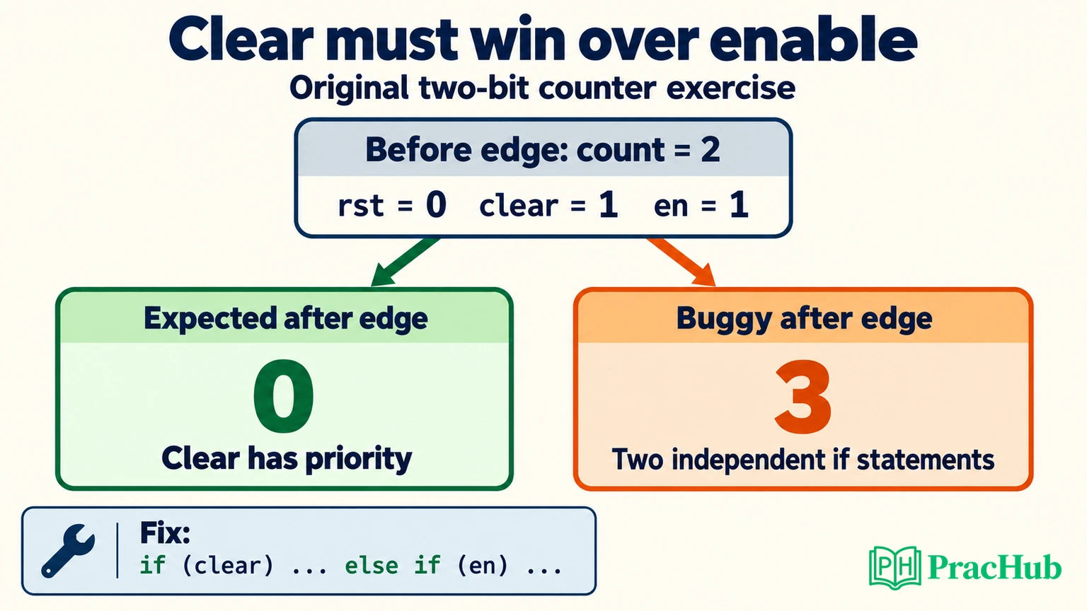
At edge five, the previous count is two and both clear and enable are high. In this same procedural block, both assignments execute; the later nonblocking assignment determines the final scheduled value. The right-hand expression uses the old count, so the result is three, not the required zero.
This is a priority bug. Replacing the second if with else if restores the intended exclusion. The correction should follow from the specification, not from a preference for a particular coding style.
When inspecting a waveform, start at the first divergence rather than the final failed assertion. Record the previous count, clock edge, sampled controls, expected next value, and observed next value. Then ask whether the disagreement belongs to the DUT, stimulus, reference model, or observation timing.
If the observed count is two immediately at the edge but becomes zero after the update, investigate the checker schedule. If it settles at three, the priority defect is consistent with the evidence. If clear never reached the interface, investigate stimulus delivery. These observations lead to different fixes despite the same initial “count mismatch” message.
Save a minimal reproducer, input sequence or random seed, build configuration, and relevant waveform window. After fixing the defect, rerun the failing case and neighboring priority cases. A green rerun without understanding the cause does not establish that the bug is gone.
Assertions and coverage: explain what your evidence proves
Describe properties in precise temporal language before writing assertion syntax. For this block: reset at the active edge must produce zero after the update; clear without reset must also produce zero; an enabled cycle without either control must increment modulo four; a disabled cycle without either control must hold.
If you write concurrent assertions, explain how sampled values and implication timing align with the register update. An assertion that compares a pre-update sample against a post-update expectation is not rescued by having the right English comment.
Coverage answers a different question from checking. A bin for “clear and enable together” shows that the scenario occurred; the comparison establishes whether priority was correct. Track both control combinations and relevant previous states. A test that toggles every input can still miss clearing from a nonzero value.
When asked whether verification is complete, state the boundary. The counter exercise has one clock, synchronous reset, and a small binary state space. It says nothing about metastability or asynchronous FIFO correctness. For those topics, define the clock relationship and transfer protocol before proposing a synchronizer or assertion.
Connect the exercise to your project and the emulation role
The official posting's emulation context makes it useful to explain what you would preserve when moving from a small simulation to a larger verification environment: the intended behavior, reproducible stimulus, expected results, and a way to localize failures. Do not assume that an arbitrary simulation-only delay or visibility mechanism transfers unchanged.
Prepare one real project story with a concrete failing observation. Explain what you owned, which hypothesis you tested first, why it was wrong or right, and what regression evidence supported the fix. Coursework and student hardware projects are valid examples when you describe their scope honestly.
If you mention C++ or Python tooling, connect it to work you can explain: parsing logs, generating stimulus, comparing traces, or reducing a failure. Be ready to discuss malformed input, deterministic output, and a test for the tool itself. A verification utility can introduce a false result just as a testbench can.
Five PracHub questions for focused follow-up
This set combines one NVIDIA hardware-oriented record with cross-company ASIC and debugging practice. It is not a verified question list for the JR2020640 hiring loop. Use the broader ASIC question as a reference map rather than memorizing its entire answer.
| PracHub question | Preparation focus |
|---|---|
| ASIC Verification Fundamentals Across SystemVerilog UVM CDC and Architecture | Identify gaps in scheduling, testbench methodology, and architecture. |
| Explain SystemVerilog verification concepts and write constraints | Explain constraint intent and sampling assumptions. |
| Describe common RTL lint warnings and errors | Investigate width mismatches and structural warnings. |
| Design signals across power and clock domains | Extend beyond the single-clock exercise with explicit crossing assumptions. |
| Describe your most memorable bug and fix | Tell a debugging story grounded in evidence and personal contribution. |
Start with the SystemVerilog verification exercise, then explain one small design using a contract, a trace, and a failing case. Those three artifacts give an interviewer something concrete to challenge—and give you a clear basis for defending your reasoning.
Sources and Further Reading
- NVIDIA ASIC Verification Engineer, New College Grad 2026, JR2020640 — official Emulation-team role; checked September 8, 2026.
- NVIDIA second-round ASIC verification discussion — limited firsthand new-grad report from July 2026, not a completed-loop account.
- Accellera UVM 1.2 User's Guide — historical primary methodology reference for verification components.
Comments (0)